Sheet 01 — Projects / Fig. 1
Teleoperation Board
A PCB that lets a Raspberry Pi drive Cornell Electric Vehicles' competition car remotely: steering, speed, and braking.
- When
- 2026-08 — ongoing
- Stack
- AltiumRP2040Raspberry PiC
- Tags
- PCB designEmbeddedAutonomy
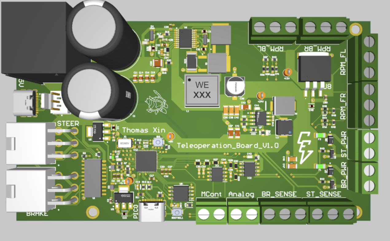
This printed circuit board (PCB) drives Cornell Electric Vehicles' normally human-operated competition car remotely in tandem with a Raspberry Pi. It was created as a test bed for Cornell Electric Vehicles' autonomy demo at Shell Eco Marathon planned for April 2027 as a first step in bringing Southwest Research Institute's European autonomous driving competition to the US.
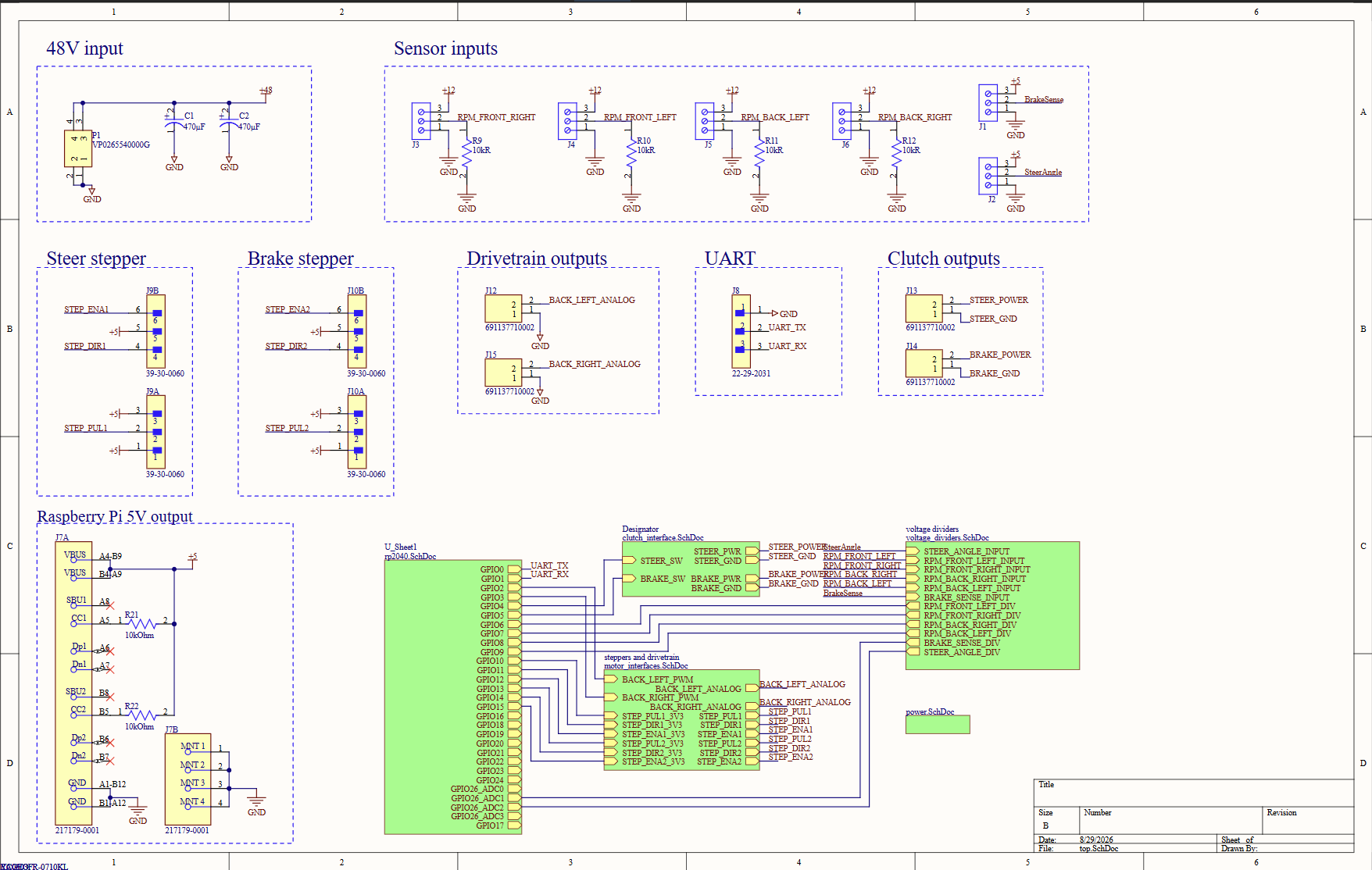 FULL SIZE
§1Power
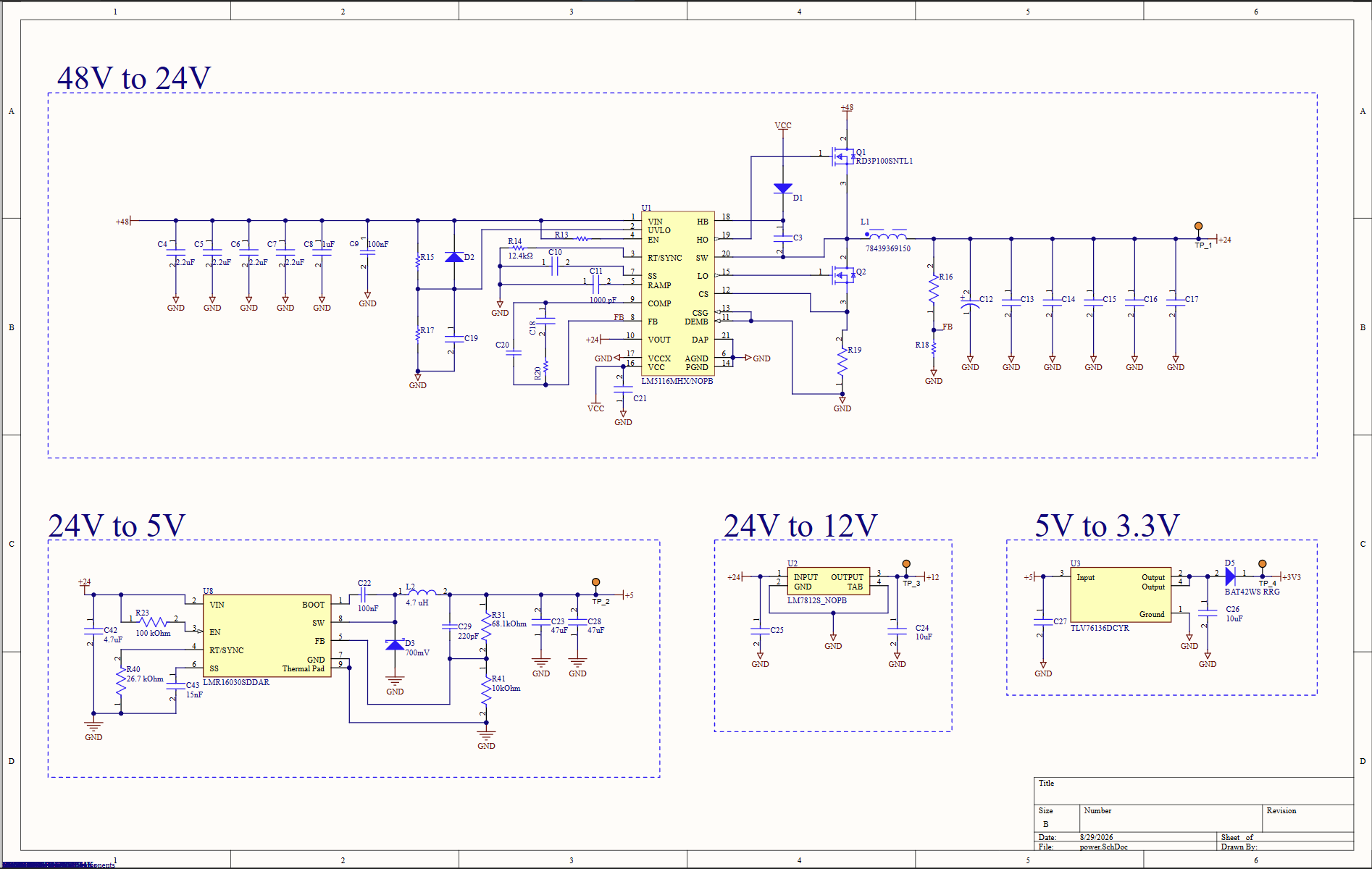
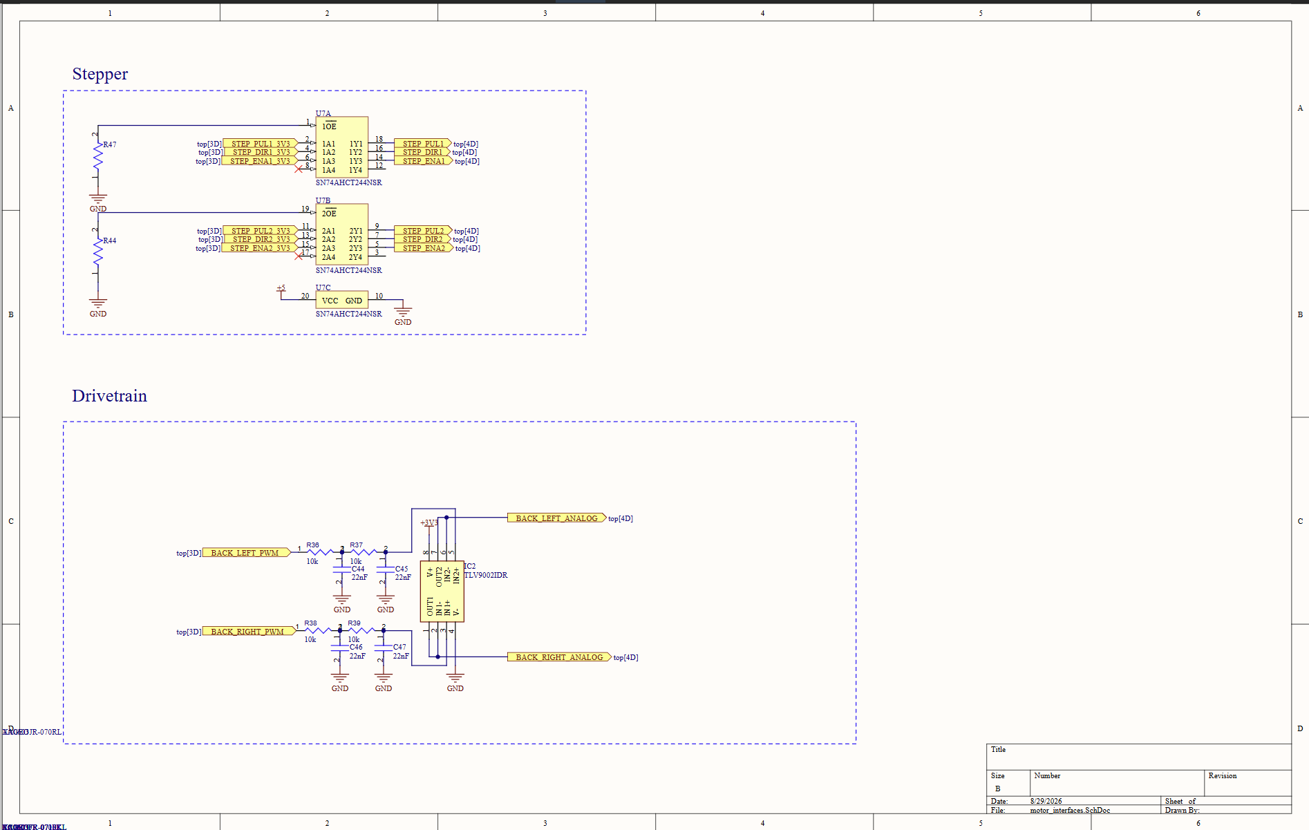
The board is powered with a 48-60V power source or battery and powers 24V electromagnetic clutches, 12V optical RPM sensors, 5V analog steering wheel angle and hydraulic brake pressure sensors, 5V stepper motor driver controls, a 5V analog drivetrain power signal, and a 3.3V logic level for the RP2040 microcontroller. To power all of these rails, the board has two buck converters: 48/60V --> 24V, and 24V --> 5V. It then has three Low-Dropout Regulators (LDOs): one 24V --> 12V and two 5V --> 3.6V, one of which goes from the 5V rail to the 3.3V rail, and one of which goes from the microcontroller's 5V USB C flash port. Both go through Schottky diodes with 0.3V voltage drops to prevent noise from the board's 5V rail from frying my computer's USB port while flashing firmware to the board. The choice to use LDOs versus buck converters comes from the
 FULL SIZE
§2Microcontroller
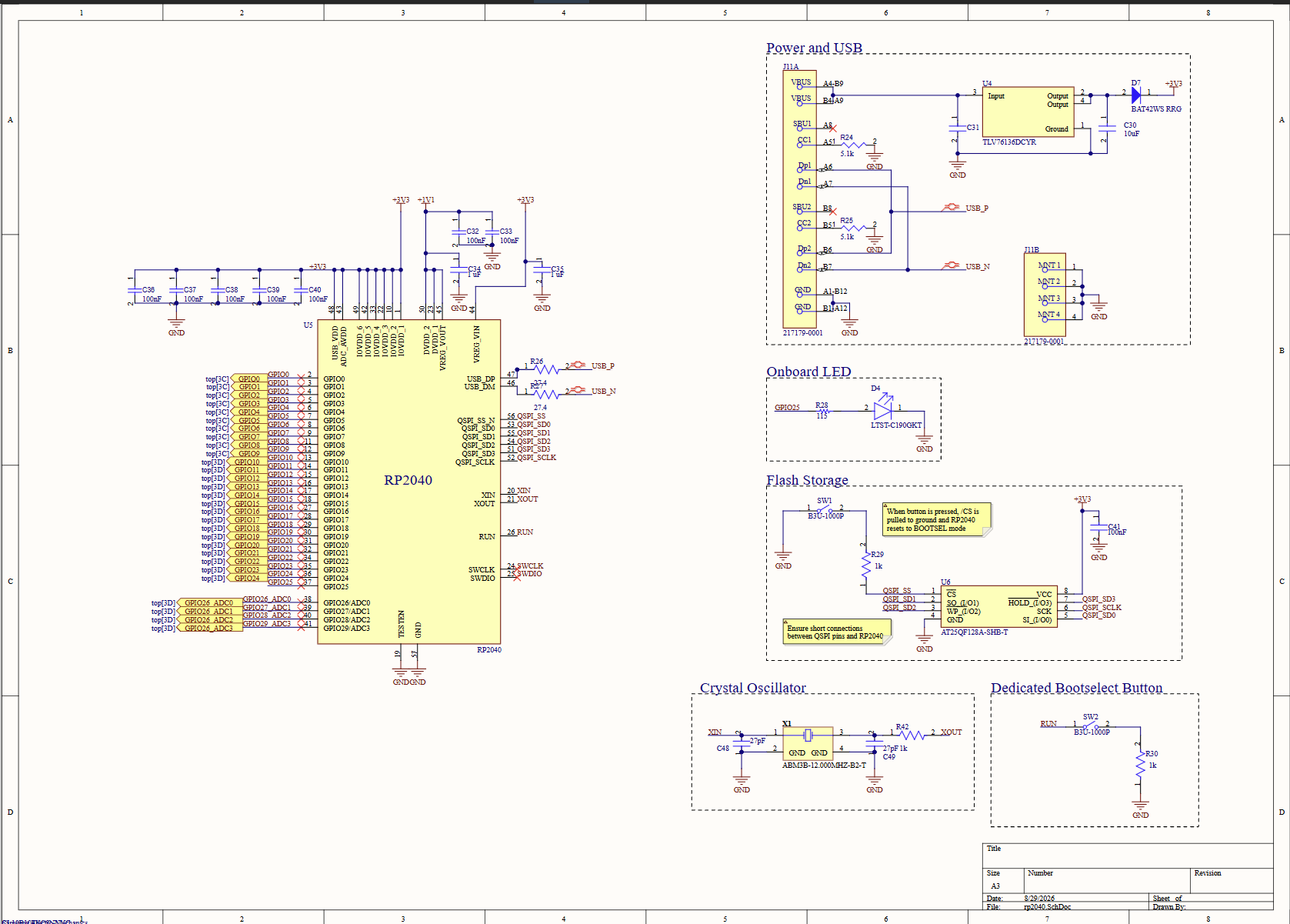
The team's microcontroller of choice is the RP2040, so this board follows that standard. The chip is responsible for inputting and fulfilling steering, velocity, and braking commands from a Raspberry Pi (which has a gamepad plugged into it for the initial version of this project), as well as communicating sensor readings back to the Pi for live telemetry. The commands are fulfilled with three separate PID controllers for velocity, steering, and braking. The board communicates to the Pi via USB serial, which has built-in error handling and better wire insulation than the SPI or UART options we had on hand.
 FULL SIZE
§3Actuators and sensing
 FULL SIZE
 FULL SIZE
 FULL SIZE
§4Layout
 FULL SIZE